User Tools
Table of Contents
COLORING MIDRES BITMAPS
INTRODUCING PALETTES
The most popular way to color an image is to describe the color for each pixel, and this is usually done using the 8-bit per component RGB format. This means that we are going to use one byte to describe the luminance level for each of the RGB channels, for a total of three bytes per pixel.
The “palette” is a correspondence table, in which the colors us selected from a range of possible colors (as described according to the RGB logic) and that are assigned to an index, on the basis of which it is possible to refer to the pixel colour. Using an index requires less space, and it is a technique that aims to reduce memory usage, processing load, bandwidth, as well as RAM or mass storage usage.
Retrocomputers usually have a fixed palette, made up of a limited and preprogrammed set of colors. This implies that the representation of the original colors occurs by “adapting” the color, or by selecting a neighboring one.
In the Commodore 64, for example, the palette consists of 16 colors while in the Commodore VIC 20 the palette is limited to just 8 colors.
COLOR MAPPING
As we described in the other topic, “midres” bitmaps are made up of black and white mixels, where the value 1 indicates white and the value 0 indicates black. Since the “midres” uses the text mode, which foresees being able to define a different color chosen from a palette for each character, the mixels can be colored in groups of 2×2.
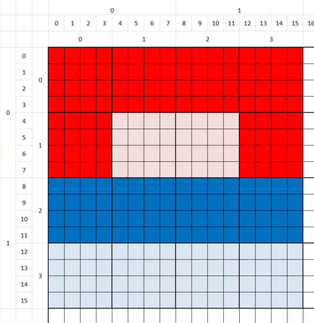
In this figure, for example, we can see the coloring of 16 mixels. The mixels in line 0 are red. So are the mixels in position (0,1) and (3,1). The mixels in row 2, on the other hand, are blue.
Note that the remaining mixels are off and are therefore black, but they are represented on the diagram with a more subdued color. This serves to underline how, if they were turned on, they would assume the color relative to the character they belong to.
This implies that the coloring of the images is inaccurate, and undergoes a phenomenon called “color clash”.
COLORING A MIXEL
Coloring a mixel is a less precise process than drawing one, and this is due to the fact that the color of a mixel depends on the color of the character that the mixel belongs to.
We start by identifying the coordinates of the character on the screen to which the mixel that we want to color refers to at the coordinates (x, y). Supposing you are working with an 8×8 pixel character and a 2×2 mixel matrix per character, the character is obtained by dividing the coordinates by 2:
  mx = _x >> 1;
  my = _y >> 1;
At this point, it is possible to actually color the semigraphic character, and the new color will be used to replace the previous one.
_screen[my * WIDTH + mx] = _color + BRIGHTNESS;
EXAMPLE
Take, for example, the following PNG image (800×500 pixels, 24 bpp):

You can use the program img2midres to convert this image into two files (-o, -O) that can be directly loaded into memory (-u) with an indexed palette midres for the Commodore 64 (-64):
img2midres64.exe -64 -u -i image06.png -o image6406c.pic -O image6406c.col
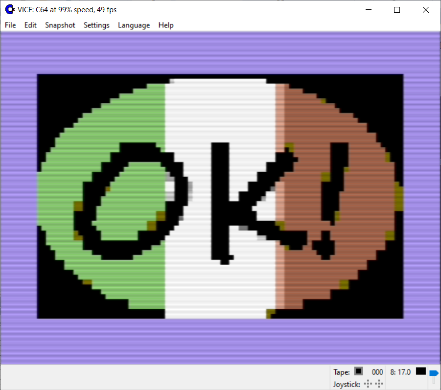
Once the two files have been placed on a disk, it will be possible to write a short BASIC program:
  10 if p=0 then 50
  20 if c=0 then 60
  30 poke 53281,0
  40 goto 40
  50 p=1:load "image6406c.pic",8,1
  60 c=1:load "image6406c.col",8,1
This is the result you get:
If you have a VIC 20, you can use the same program img2midres to convert this image into two files (-o, -O) that can be directly loaded into memory (-u) with with an indexed palette midres for the VIC 20 (-20):
img2midres64.exe -20 -u -i image06.png -o image2006c.pic -O image2006c.col
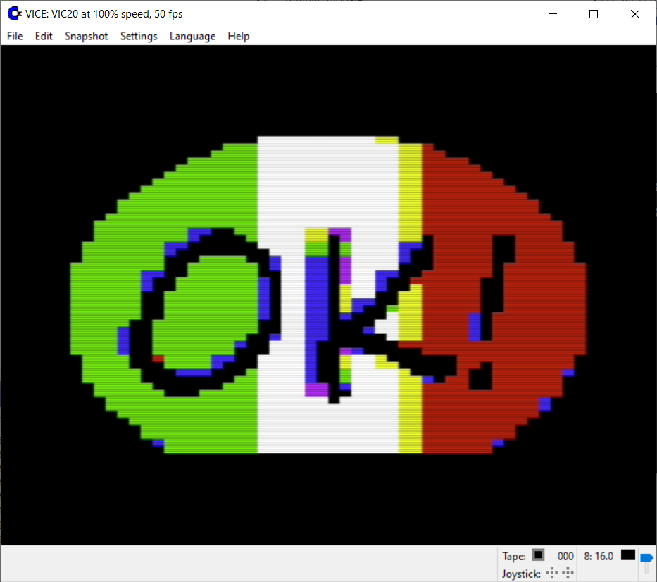
Once the two files have been placed on a disk, it will be possible to write a short BASIC program:
  5 if i=0 then 45
  10 if p=0 then 50
  20 if c=0 then 60
  30 poke 36879,8
  40 goto 40
  45 for i=0 to 23*22:print " ";:next i
  50 p=1:load "image2006c.pic",8,1
  60 c=1:load "image2006c.col",8,1
This is the result you get:
COLOR CLASH
The “color clash” is, in general, a phenomenon caused by the limitations in the graphics circuits of some retrocomputers, where there is the limitation of two colors for each character that makes up the mixel set considered. This limitation arises from the particular memory layout of video processors that support text mode, designed in such a way as to minimize the use of frame buffer memory and thus optimize the display of text rather than graphics. To save memory, the bitmap and color map are stored in separate areas of memory. While the bitmap specifies the status of the individual mixels (enabled or disabled), the color information (or “attributes”) always and only corresponds to the character matrix of the text. This byte encodes, in different ways from platform to platform, the index in the palette to be used. Therefore, each block can only contain 2 colors among those available. Attempting to add a third color in the same area will overwrite the previous color.
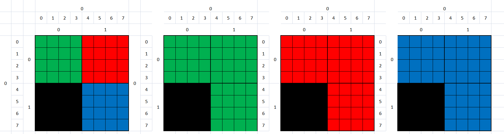
For example, if you have an image with four pixels with three different colors, the related mixels will have only one of the three colors. As a result, finely detailed color graphics are impossible, as color can only be applied in the blocks that make up the mixels. To avoid this type of conflict, static graphical displays must be constructed carefully.
Page Tools
