User Tools
midres_bitmap
Table of Contents
BASICS OF BITMAP IN MIDRES
DEFINING A MIDRES BITMAP
The basis of this technique, which has to do with a “bitmap” or “black / white” (1 bit) graphics, is based on establishing an addressing scheme for all the points accessible at the maximum resolution available on the hardware (conventionally called “hires”).
This scheme is organized according to the principle of “grouping” of matrix pixels, submultiples of the characters' size at the minimum available resolution, that is the textual resolution (conventionally called “lowres”).
This process allows to reach an intermediate resolution, which is conventionally given the name of “midres”.
MIDRES ON COMMODORE 64
For example, in the Commodore 64 we have that the text screen consists of 40 columns by 25 rows. Each character occupies an 8×8 pixel matrix.
So, the maximum resolution (“hires”) is equal to 320×200 pixels while the minimum (“lowres”) is 40×25 characters. An 8 × 8 pixel large character could be divided vertically into two halves and horizontally into as many parts.
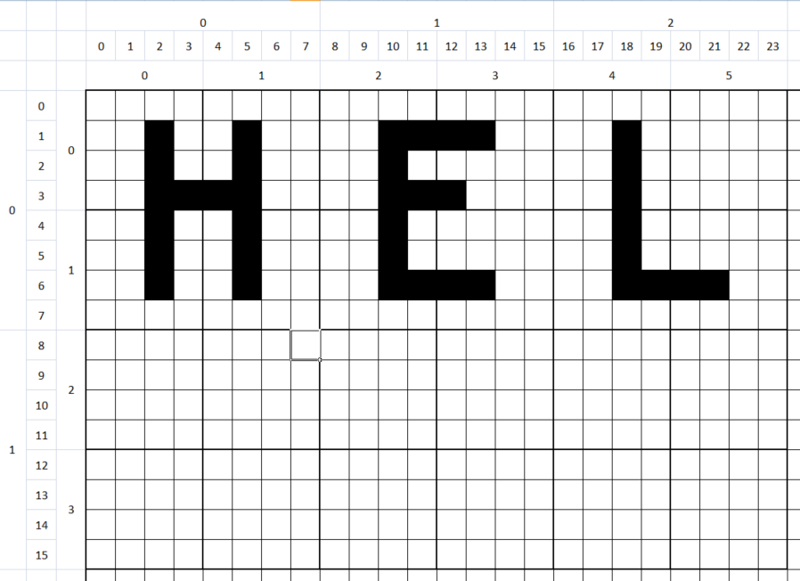
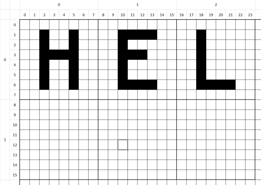
By grouping the pixels on a 4-by-4 scheme, we obtain that each character of 8×8 pixels gives space to a matrix of 2×2 “points”, which are none other than the medium resolution pixels (which we will call “midres pixels” = “mixel”). In this way, we get a screen with a resolution of 80×50 mixels.
We can therefore think of assigning a white color to bit 1 and a black color to bit 0. Since there are 4 independent “mixels” for each matrix, and since they can be switched on or off independently, we have a maximum of 2^4 = 16 combinations.
This correspondence is implemented by means of an index corresponding to the position in the character map of a matrix of the relative points.
To represent this variety, a set of special characters will be used, which visually and exhaustively represent all the binary combinations of this subdivision matrix. In other words: each “mixel” is represented by a group of high resolution 4×4 pixels, and each 2×2 mixel is represented by a specific character.
USING PETSCII
These symbols, which appear exactly as if they were drawn in raster graphics mode, are called “pseudographic characters” and are, generally, part of the character set of many retrocomputers1).
In particular in the Commodore 64 (and of the whole family of Commodore computers) we have 16 ready-made characters available, and present in the PETSCII alphabet. This implies that these characters can be displayed from the moment the computer is turned on, even when no program has yet been loaded.
DRAWING A MIXEL
Drawing a mixel is a more elaborate process than drawing a pixel, and this is due to the need to select one of the special characters that represent that specific mixel combination for that particular character.
We start by identifying the coordinates of the character on the screen to which the mixel that we want to draw refers to at the coordinates (x, y). Supposing you are working with an 8×8 pixel character and a 2×2 mixel matrix per character, the character is obtained by dividing the coordinates by 2:
  mx = _x >> 1;
  my = _y >> 1;
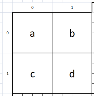
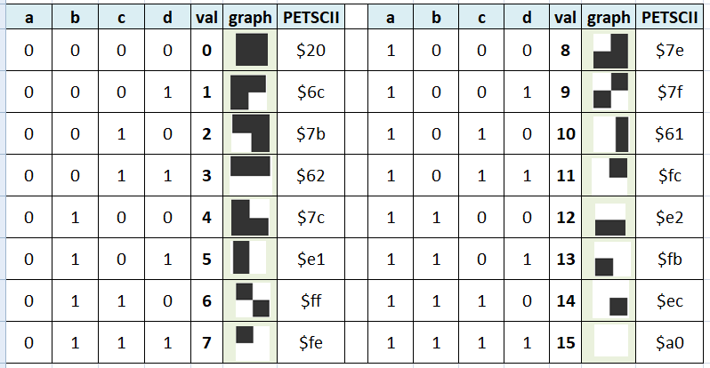
At this point it is necessary to identify which mixel, among the four that make up the character, you are interested in drawing. The mixels are conventionally represented according to the above diagram.
So, if the mixel has to be colored “on” at an even abscissa, it will be represented by the letter a or c; on the contrary, if the abscissa is odd, it will be represented by the letter b or d. At the same time, if the ordinate is even, it will be represented by the letter a or b; on the contrary, from the letter c or d. The intersection between these two sets of letters constitutes the bit to be enabled. This bit belongs to the least significant nibble (4 bit) of the byte that will be composed.
abcd = ((1 - (_x & 1)) + (1 - (_y & 1)) * 2);
At this point, it is possible to actually draw the semigraphic character. To this end, it is necessary to know which character is occupied by the current coordinates, in order to decode and update the actual pattern.
  for (i = 0; i < sizeof(RENDERED_MIXELS); ++i) {
    if (RENDERED_MIXELS[i] == _current) {
      return i;
    }
  }
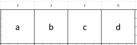
For this purpose, the system will check the set of special characters needed to identify the current pixel configuration.
currentMixelbits = currentMixelbits | (1 << _abcd);
Once the configuration has been identified, the relative bit identified by the coordinates will be set.
return RENDERED_MIXELS[currentMixelbits];
Finally, the new special character thus identified will be used to replace the previous one.
EXAMPLE
Take, for example, the following PNG image (800×500 pixels, 1 bpp):

You can use the program img2midres to convert this image into two files (-o, -O) that can be directly loaded into memory (-u) with a black and white midres bitmap (-b) for the Commodore 64 (-64):
img2midres64.exe -64 -b -u -i image05.png -o image6405b.pic -O image6405b.col
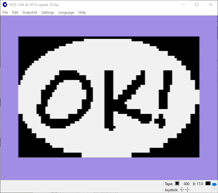
Once the two files have been placed on a disk, it will be possible to write a short BASIC program:
  10 if p=0 then 50
  20 if c=0 then 60
  30 poke 53281,0
  40 goto 40
  50 p=1:load "image6405b.pic",8,1
  60 c=1:load "image6405b.col",8,1
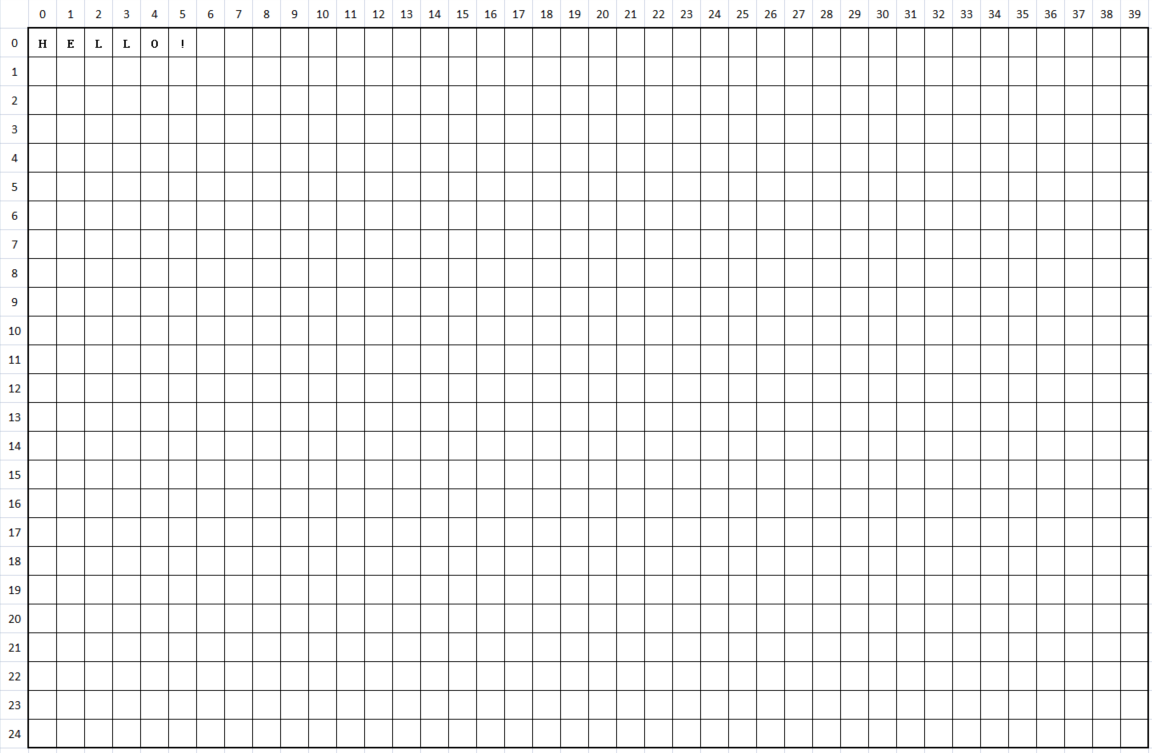
This is the result you get:
If you have a VIC 20, you can use the same program img2midres to convert this image into two files (-o, -O) that can be directly loaded into memory (-u) with a black and white midres bitmap (-b) for the VIC 20 (-20):
img2midres64.exe -20 -b -u -i image05.png -o image2005b.pic -O image2005b.col
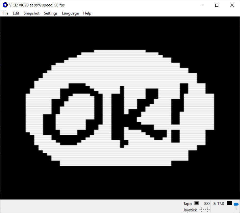
Once the two files have been placed on a disk, it will be possible to write a short BASIC program:
  5 if i=0 then 45
  10 if p=0 then 50
  20 if c=0 then 60
  30 poke 36879,8
  40 goto 40
  45 for i=0 to 23*22:print " ";:next i
  50 p=1:load "image2005b.pic",8,1
  60 c=1:load "image2005b.col",8,1
This is the result you get:
USING OTHER HARDWARE
Depending on the hardware used, similar semigraphic characters may be present, or we could need a preventive reprogramming of the video hardware, in order to convert the character set to reproduce the bit pattern as described. In some hardware, the number of semigraphic characters needed could be halved in the presence of a “reverse” attribute, since half of the characters are the logical inverse of the other half.
Other tricks used to decrease the number of characters needed are:
- use the 0x20 (32, space) character as “all bits are zero”;
- use the character 0x7f (127, inverted space) as “all bits are one” 2)
1)
This approach was later adopted, in later times, in the UNICODE standard such as in the Unicode Block Elements block.
2)
The use of the hexadecimal character 0x7f (decimal 127) to indicate “all pixels to one” is linked to the nature of paper tapes: infact, when the tape was used and punching it to represent information, all seven holes were punched with that value, creating the hexadecimal “byte” 0x7f, considered another way to erase the character. Subsequently, the same code was used by the graphic subsystem designers to represent the cursor on the screen.
Page Tools
Except where otherwise noted, content on this wiki is licensed under the following license: CC Attribution-Noncommercial-Share Alike 4.0 International
